How to Upload Program to Arduino Without It Running Immediately
Watch Now This tutorial has a related video course created by the Existent Python team. Watch information technology together with the written tutorial to deepen your understanding: Arduino With Python: How to Get Started
Microcontrollers have been around for a long time, and they're used in everything from complex machinery to common household appliances. All the same, working with them has traditionally been reserved for those with formal technical training, such as technicians and electrical engineers. The emergence of Arduino has made electronic application design much more accessible to all developers. In this tutorial, you'll notice how to use Arduino with Python to develop your ain electronic projects.
You'll embrace the basics of Arduino with Python and learn how to:
- Set up electronic circuits
- Set up the Firmata protocol on Arduino
- Write basic applications for Arduino in Python
- Command analog and digital inputs and outputs
- Integrate Arduino sensors and switches with higher-level apps
- Trigger notifications on your PC and ship emails using Arduino
The Arduino Platform
Arduino is an open-source platform composed of hardware and software that allows for the rapid development of interactive electronics projects. The emergence of Arduino drew the attention of professionals from many different industries, contributing to the kickoff of the Maker Movement.
With the growing popularity of the Maker Movement and the concept of the Cyberspace of Things, Arduino has become one of the main platforms for electronic prototyping and the development of MVPs.
Arduino uses its own programming language, which is similar to C++. However, it'south possible to utilize Arduino with Python or another high-level programming language. In fact, platforms similar Arduino work well with Python, especially for applications that require integration with sensors and other physical devices.
All in all, Arduino and Python can facilitate an effective learning environment that encourages developers to get into electronics design. If yous already know the basics of Python, then y'all'll be able to go started with Arduino by using Python to command it.
The Arduino platform includes both hardware and software products. In this tutorial, y'all'll use Arduino hardware and Python software to acquire about basic circuits, equally well as digital and analog inputs and outputs.
Arduino Hardware
To run the examples, you lot'll need to get together the circuits by hooking up electronic components. Y'all tin generally find these items at electronic component stores or in good Arduino starter kits. Y'all'll need:
- An Arduino Uno or other compatible board
- A standard LED of any colour
- A push push button
- A ten KOhm potentiometer
- A 470 Ohm resistor
- A 10 KOhm resistor
- A breadboard
- Jumper wires of diverse colors and sizes
Let's take a closer look at a few of these components.
Component 1 is an Arduino Uno or other uniform lath. Arduino is a project that includes many boards and modules for different purposes, and Arduino Uno is the most basic amongst these. Information technology'south besides the most used and most documented board of the whole Arduino family, so information technology'south a dandy option for developers who are just getting started with electronics.
Components 5 and six are resistors. About resistors are identified by colored stripes according to a color code. In general, the outset three colors represent the value of a resistor, while the fourth colour represents its tolerance. For a 470 Ohm resistor, the showtime three colors are yellow, violet, and brown. For a x KOhm resistor, the start three colors are brown, black, and orange.
Component 7 is a breadboard, which you use to claw up all the other components and assemble the circuits. While a breadboard is not required, it'due south recommended that you get one if yous intend to begin working with Arduino.
Arduino Software
In addition to these hardware components, you'll demand to install some software. The platform includes the Arduino IDE, an Integrated Development Environment for programming Arduino devices, amidst other online tools.
Arduino was designed to allow you to program the boards with picayune difficulty. In general, you'll follow these steps:
- Connect the board to your PC
- Install and open the Arduino IDE
- Configure the board settings
- Write the code
- Printing a button on the IDE to upload the plan to the board
To install the Arduino IDE on your calculator, download the appropriate version for your operating organization from the Arduino website. Check the documentation for installation instructions:
- If you're using Windows, and so apply the Windows installer to ensure you download the necessary drivers for using Arduino on Windows. Cheque the Arduino documentation for more details.
- If you're using Linux, so you may have to add your user to some groups in guild to use the serial port to program Arduino. This process is described in the Arduino install guide for Linux.
- If you're using macOS, then you can install Arduino IDE past post-obit the Arduino install guide for OS X.
At present that you lot've installed the Arduino IDE and gathered all the necessary components, y'all're ready to become started with Arduino! Side by side, you'll upload a "Hello, World!" program to your lath.
"Hello, Earth!" With Arduino
The Arduino IDE comes with several example sketches you tin can utilise to learn the basics of Arduino. A sketch is the term y'all use for a program that you can upload to a board. Since the Arduino Uno doesn't have an attached display, you'll need a fashion to encounter the concrete output from your program. Y'all'll utilize the Blink example sketch to brand a built-in LED on the Arduino board blink.
Uploading the Blink Example Sketch
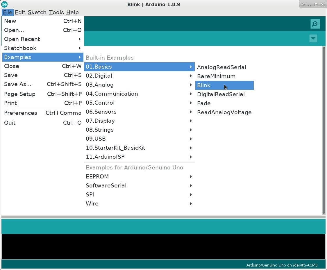
To become started, connect the Arduino lath to your PC using a USB cable and outset the Arduino IDE. To open the Glimmer example sketch, access the File carte du jour and select Examples, then 01.Nuts and, finally, Blink:
The Blink example lawmaking will exist loaded into a new IDE window. Only before you can upload the sketch to the lath, you'll need to configure the IDE past selecting your board and its continued port.
To configure the lath, access the Tools menu and then Board. For Arduino Uno, yous should select Arduino/Genuino Uno:

Afterwards you select the lath, you accept to set the appropriate port. Admission the Tools bill of fare once more, and this time select Port:

The names of the ports may be different, depending on your operating organisation. In Windows, the ports volition exist named COM4, COM5, or something similar. In macOS or Linux, you may run into something like /dev/ttyACM0 or /dev/ttyUSB0. If you have whatever bug setting the port, then take a look at the Arduino Troubleshooting Folio.
Later you've configured the board and port, you lot're all set to upload the sketch to your Arduino. To practise that, you just accept to press the Upload button in the IDE toolbar:

When you printing Upload, the IDE compiles the sketch and uploads it to your board. If you want to check for errors, then y'all can printing Verify before Upload, which volition only compile your sketch.
The USB cable provides a serial connectedness to both upload the program and ability the Arduino board. During the upload, you lot'll meet LEDs flashing on the lath. After a few seconds, the uploaded program volition run, and y'all'll see an LED light glimmer once every second:
After the upload is finished, the USB cable will continue to power the Arduino board. The programme is stored in wink memory on the Arduino microcontroller. You can besides utilize a bombardment or other external ability supply to run the application without a USB cable.
Connecting External Components
In the previous department, you used an LED that was already present on the Arduino board. However, in most applied projects you'll need to connect external components to the board. To make these connections, Arduino has several pins of dissimilar types:

Although these connections are commonly called pins, you can see that they're non exactly concrete pins. Rather, the pins are holes in a socket to which you can connect jumper wires. In the figure in a higher place, you tin run across different groups of pins:
- Orange rectangle: These are 13 digital pins that yous can use as inputs or outputs. They're only meant to piece of work with digital signals, which accept 2 different levels:
- Level 0: represented by the voltage 0V
- Level 1: represented by the voltage 5V
- Green rectangle: These are 6 analog pins that you can apply every bit analog inputs. They're meant to work with an capricious voltage betwixt 0V and 5V.
- Blue rectangle: These are 5 power pins. They're mainly used for powering external components.
To get started using external components, you'll connect an external LED to run the Blink example sketch. The built-in LED is connected to digital pin #xiii. Then, allow's connect an external LED to that pivot and check if it blinks. (A standard LED is i of the components you saw listed before.)
Before yous connect anything to the Arduino board, it's good practice to disconnect it from the computer. With the USB cable unplugged, you lot'll exist able to connect the LED to your lath:

Note that the figure shows the lath with the digital pins now facing you.
Using a Breadboard
Electronic circuit projects commonly involve testing several ideas, with you adding new components and making adjustments as you get. However, it can be tricky to connect components directly, especially if the excursion is large.
To facilitate prototyping, you can apply a breadboard to connect the components. This is a device with several holes that are continued in a particular way so that y'all can easily connect components using jumper wires:

You can come across which holes are interconnected past looking at the colored lines. You'll use the holes on the sides of the breadboard to ability the circuit:
- Connect one hole on the red line to the power source.
- Connect 1 hole on the blue line to the ground.
And then, you can easily connect components to the power source or the footing by but using the other holes on the cherry-red and blue lines. The holes in the middle of the breadboard are connected as indicated past the colors. You lot'll employ these to make connections betwixt the components of the circuit. These two internal sections are separated past a pocket-size depression, over which you can connect integrated circuits (ICs).
You can employ a breadboard to assemble the circuit used in the Blink example sketch:

For this circuit, information technology's important to note that the LED must exist continued according to its polarity or information technology won't work. The positive last of the LED is chosen the anode and is by and large the longer one. The negative terminal is chosen the cathode and is shorter. If you're using a recovered component, then yous can as well identify the terminals past looking for a flat side on the LED itself. This will indicate the position of the negative concluding.
When y'all connect an LED to an Arduino pivot, you'll always need a resistor to limit its current and avert called-for out the LED prematurely. Here, yous use a 470 Ohm resistor to do this. You can follow the connections and check that the circuit is the same:
- The resistor is continued to digital pivot 13 on the Arduino lath.
- The LED anode is connected to the other last of the resistor.
- The LED cathode is connected to the ground (GND) via the blue line of holes.
For a more detailed explanation, check out How to Use a Breadboard.
Later on y'all finish the connection, plug the Arduino back into the PC and re-run the Blink sketch:
As both LEDs are continued to digital pivot 13, they blink together when the sketch is running.
"Hello, Earth!" With Arduino and Python
In the previous section, you lot uploaded the Blink sketch to your Arduino board. Arduino sketches are written in a linguistic communication similar to C++ and are compiled and recorded on the wink memory of the microcontroller when you press Upload. While you can utilize another language to straight plan the Arduino microcontroller, it's not a petty job!
Nonetheless, there are some approaches you tin accept to utilise Arduino with Python or other languages. 1 thought is to run the main program on a PC and use the serial connection to communicate with Arduino through the USB cablevision. The sketch would be responsible for reading the inputs, sending the information to the PC, and getting updates from the PC to update the Arduino outputs.
To control Arduino from the PC, you'd have to design a protocol for the communication betwixt the PC and Arduino. For instance, you could consider a protocol with messages like the following:
- VALUE OF Pin thirteen IS HIGH: used to tell the PC virtually the status of digital input pins
- Set PIN 11 LOW: used to tell Arduino to fix the states of the output pins
With the protocol defined, you could write an Arduino sketch to send messages to the PC and update the states of the pins according to the protocol. On the PC, you could write a program to command the Arduino through a series connection, based on the protocol you've designed. For this, you can use whatever language and libraries you lot prefer, such equally Python and the PySerial library.
Fortunately, there are standard protocols to do all this! Firmata is ane of them. This protocol establishes a serial advice format that allows you lot to read digital and analog inputs, likewise as send information to digital and analog outputs.
The Arduino IDE includes prepare-made sketches that will bulldoze Arduino through Python with the Firmata protocol. On the PC side, in that location are implementations of the protocol in several languages, including Python. To get started with Firmata, allow's use it to implement a "Hello, World!" programme.
Uploading the Firmata Sketch
Before you write your Python programme to drive Arduino, you accept to upload the Firmata sketch so that you can employ that protocol to command the lath. The sketch is available in the Arduino IDE's built-in examples. To open up it, admission the File menu, so Examples, followed past Firmata, and finally StandardFirmata:

The sketch volition be loaded into a new IDE window. To upload it to the Arduino, you tin follow the same steps yous did before:
- Plug the USB cable into the PC.
- Select the appropriate lath and port on the IDE.
- Printing Upload.
After the upload is finished, you won't notice any activity on the Arduino. To control information technology, you lot still need a program that can communicate with the board through the serial connection. To work with the Firmata protocol in Python, you'll need the pyFirmata package, which you lot tin can install with pip:
Later the installation finishes, you tin run an equivalent Blink application using Python and Firmata:
ane import pyfirmata 2 import fourth dimension 3 4 lath = pyfirmata . Arduino ( '/dev/ttyACM0' ) 5 6 while Truthful : 7 board . digital [ 13 ] . write ( i ) eight time . sleep ( 1 ) 9 board . digital [ 13 ] . write ( 0 ) 10 time . sleep ( one ) Here's how this programme works. You import pyfirmata and employ it to institute a serial connection with the Arduino board, which is represented by the lath object in line 4. You also configure the port in this line by passing an argument to pyfirmata.Arduino(). You can use the Arduino IDE to find the port.
lath.digital is a listing whose elements represent the digital pins of the Arduino. These elements have the methods read() and write(), which volition read and write the state of the pins. Like nigh embedded device programs, this program mainly consists of an infinite loop:
- In line 7, digital pivot 13 is turned on, which turns the LED on for ane 2nd.
- In line 9, this pin is turned off, which turns the LED off for one second.
At present that you know the basics of how to control an Arduino with Python, permit'due south go through some applications to interact with its inputs and outputs.
Reading Digital Inputs
Digital inputs can have but two possible values. In a circuit, each of these values is represented by a dissimilar voltage. The table below shows the digital input representation for a standard Arduino Uno board:
| Value | Level | Voltage |
|---|---|---|
| 0 | Low | 0V |
| ane | High | 5V |
To command the LED, yous'll use a push to send digital input values to the Arduino. The push button should ship 0V to the board when it's released and 5V to the board when it's pressed. The figure below shows how to connect the button to the Arduino board:

You may find that the LED is continued to the Arduino on digital pin 13, merely like before. Digital pin 10 is used as a digital input. To connect the push, you take to use the 10 KOhm resistor, which acts as a pull downwardly in this circuit. A pull down resistor ensures that the digital input gets 0V when the button is released.
When you release the button, yous open the connection between the two wires on the button. Since there's no current flowing through the resistor, pin 10 only connects to the ground (GND). The digital input gets 0V, which represents the 0 (or low) state. When y'all printing the push, you employ 5V to both the resistor and the digital input. A current flows through the resistor and the digital input gets 5V, which represents the 1 (or high) country.
Y'all can utilise a breadboard to get together the in a higher place circuit as well:

Now that y'all've assembled the circuit, you have to run a program on the PC to control information technology using Firmata. This program will plow on the LED, based on the state of the button button:
1 import pyfirmata 2 import time 3 4 board = pyfirmata . Arduino ( '/dev/ttyACM0' ) 5 6 it = pyfirmata . util . Iterator ( lath ) 7 it . commencement () 8 ix board . digital [ ten ] . manner = pyfirmata . INPUT 10 11 while Truthful : 12 sw = board . digital [ ten ] . read () xiii if sw is Truthful : xiv board . digital [ 13 ] . write ( 1 ) 15 else : 16 board . digital [ 13 ] . write ( 0 ) 17 fourth dimension . sleep ( 0.ane ) Let's walk through this programme:
- Lines 1 and 2 import
pyfirmataandtime. - Line 4 uses
pyfirmata.Arduino()to set the connectedness with the Arduino board. - Line vi assigns an iterator that will be used to read the status of the inputs of the circuit.
- Line 7 starts the iterator, which keeps a loop running in parallel with your main code. The loop executes
board.iterate()to update the input values obtained from the Arduino board. - Line 9 sets pin 10 as a digital input with
pyfirmata.INPUT. This is necessary since the default configuration is to utilize digital pins as outputs. - Line eleven starts an infinite
whileloop. This loop reads the status of the input pin, stores information technology insw, and uses this value to turn the LED on or off by changing the value of pin 13. - Line 17 waits 0.1 seconds between iterations of the
whileloop. This isn't strictly necessary, but it's a nice trick to avoid overloading the CPU, which reaches 100% load when at that place isn't a look command in the loop.
pyfirmata also offers a more compact syntax to piece of work with input and output pins. This may be a good pick for when you're working with several pins. Y'all tin can rewrite the previous program to accept more compact syntax:
1 import pyfirmata 2 import fourth dimension 3 4 board = pyfirmata . Arduino ( '/dev/ttyACM0' ) v 6 it = pyfirmata . util . Iterator ( board ) 7 information technology . get-go () 8 9 digital_input = lath . get_pin ( 'd:x:i' ) 10 led = board . get_pin ( 'd:13:o' ) xi 12 while True : 13 sw = digital_input . read () 14 if sw is True : 15 led . write ( 1 ) 16 else : 17 led . write ( 0 ) 18 time . sleep ( 0.one ) In this version, you use lath.get_pin() to create 2 objects. digital_input represents the digital input state, and led represents the LED country. When you run this method, yous have to laissez passer a string argument equanimous of iii elements separated by colons:
- The type of the pin (
afor analog ordfor digital) - The number of the pin
- The mode of the pin (
ifor input orofor output)
Since digital_input is a digital input using pivot 10, yous pass the argument 'd:10:i'. The LED state is set up to a digital output using pivot xiii, and so the led argument is 'd:13:o'.
When you lot use board.get_pin(), in that location's no need to explicitly gear up pivot 10 every bit an input similar you did earlier with pyfirmata.INPUT. After the pins are prepare, you can access the status of a digital input pin using read(), and prepare the status of a digital output pin with write().
Digital inputs are widely used in electronics projects. Several sensors provide digital signals, similar presence or door sensors, that can exist used as inputs to your circuits. However, in that location are some cases where you'll need to mensurate analog values, such equally distance or concrete quantities. In the next section, you'll meet how to read analog inputs using Arduino with Python.
Reading Analog Inputs
In contrast to digital inputs, which tin can merely exist on or off, analog inputs are used to read values in some range. On the Arduino Uno, the voltage to an analog input ranges from 0V to 5V. Appropriate sensors are used to mensurate physical quantities, such as distances. These sensors are responsible for encoding these physical quantities in the proper voltage range so they tin exist read past the Arduino.
To read an analog voltage, the Arduino uses an analog-to-digital converter (ADC), which converts the input voltage to a digital number with a fixed number of bits. This determines the resolution of the conversion. The Arduino Uno uses a x-bit ADC and tin determine 1024 different voltage levels.
The voltage range for an analog input is encoded to numbers ranging from 0 to 1023. When 0V is applied, the Arduino encodes it to the number 0. When 5V is applied, the encoded number is 1023. All intermediate voltage values are proportionally encoded.
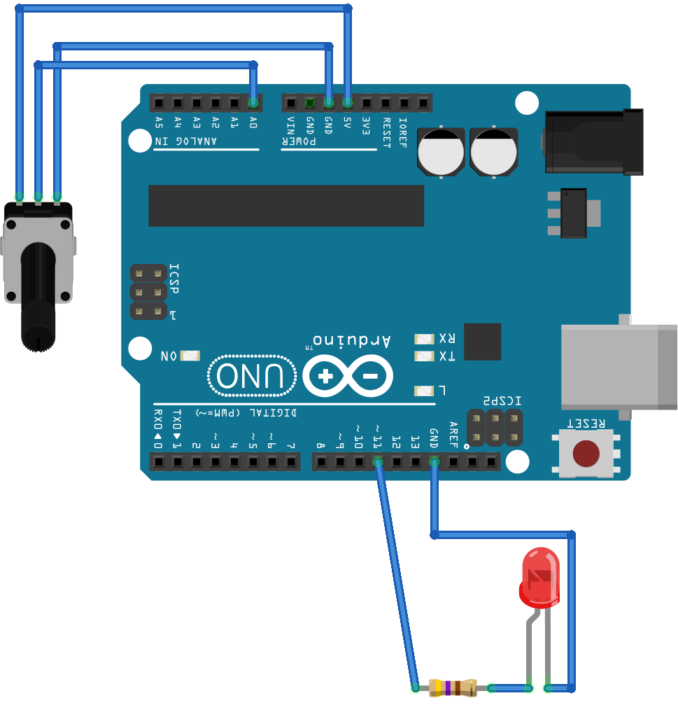
A potentiometer is a variable resistor that you can use to set the voltage applied to an Arduino analog input. You'll connect information technology to an analog input to control the frequency of a blinking LED:

In this excursion, the LED is set just as before. The end terminals of the potentiometer are connected to ground (GND) and 5V pins. This style, the key terminal (the cursor) tin can take any voltage in the 0V to 5V range depending on its position, which is continued to the Arduino on analog pin A0.
Using a breadboard, you can get together this circuit every bit follows:

Before you control the LED, you tin can utilise the circuit to bank check the different values the Arduino reads, based on the position of the potentiometer. To practice this, run the following programme on your PC:
1 import pyfirmata 2 import time 3 iv board = pyfirmata . Arduino ( '/dev/ttyACM0' ) five information technology = pyfirmata . util . Iterator ( board ) half dozen information technology . start () 7 8 analog_input = board . get_pin ( 'a:0:i' ) 9 10 while True : 11 analog_value = analog_input . read () 12 print ( analog_value ) xiii time . sleep ( 0.1 ) In line 8, you set analog_input as the analog A0 input pin with the statement 'a:0:i'. Inside the infinite while loop, y'all read this value, shop it in analog_value, and display the output to the console with print(). When you lot move the potentiometer while the program runs, you should output similar to this:
0.0 0.0293 0.1056 0.1838 0.2717 0.3705 0.4428 0.5064 0.5797 0.6315 0.6764 0.7243 0.7859 0.8446 0.9042 0.9677 1.0 i.0 The printed values change, ranging from 0 when the position of the potentiometer is on one end to one when it's on the other terminate. Note that these are float values, which may require conversion depending on the awarding.
To change the frequency of the blinking LED, you can apply the analog_value to command how long the LED volition exist kept on or off:
1 import pyfirmata 2 import time 3 4 board = pyfirmata . Arduino ( '/dev/ttyACM0' ) 5 it = pyfirmata . util . Iterator ( board ) half dozen it . start () 7 8 analog_input = board . get_pin ( 'a:0:i' ) ix led = lath . get_pin ( 'd:13:o' ) 10 11 while True : 12 analog_value = analog_input . read () 13 if analog_value is not None : 14 delay = analog_value + 0.01 15 led . write ( 1 ) 16 time . sleep ( delay ) 17 led . write ( 0 ) 18 time . sleep ( delay ) nineteen else : 20 time . sleep ( 0.1 ) Here, you calculate delay as analog_value + 0.01 to avert having delay equal to zip. Otherwise, it's common to go an analog_value of None during the first few iterations. To avert getting an error when running the programme, you employ a conditional in line 13 to test whether analog_value is None. Then you control the menses of the blinking LED.
Endeavour running the plan and changing the position of the potentiometer. You'll observe the frequency of the blinking LED changes:

By at present, you've seen how to use digital inputs, digital outputs, and analog inputs on your circuits. In the next section, you'll see how to utilise analog outputs.
Using Analog Outputs
In some cases, it's necessary to accept an analog output to drive a device that requires an analog signal. Arduino doesn't include a existent analog output, one where the voltage could be set to any value in a sure range. However, Arduino does include several Pulse Width Modulation (PWM) outputs.
PWM is a modulation technique in which a digital output is used to generate a signal with variable power. To do this, it uses a digital signal of constant frequency, in which the duty cycle is changed according to the desired ability. The duty cycle represents the fraction of the period in which the signal is set to high.
Non all Arduino digital pins can be used as PWM outputs. The ones that can be are identified by a tilde (~):

Several devices are designed to be driven by PWM signals, including some motors. It's even possible to obtain a real analog signal from the PWM signal if you lot use analog filters. In the previous instance, you used a digital output to turn an LED light on or off. In this section, you lot'll use PWM to control the brightness of an LED, according to the value of an analog input given by a potentiometer.
When a PWM signal is applied to an LED, its effulgence varies co-ordinate to the duty bicycle of the PWM signal. You're going to utilize the post-obit circuit:
This excursion is identical to the one used in the previous section to test the analog input, except for one deviation. Since information technology'south non possible to use PWM with pin 13, the digital output pin used for the LED is pin xi.
Yous can use a breadboard to assemble the circuit as follows:

With the circuit assembled, you can control the LED using PWM with the following program:
ane import pyfirmata ii import time three 4 lath = pyfirmata . Arduino ( '/dev/ttyACM0' ) 5 6 it = pyfirmata . util . Iterator ( board ) seven information technology . start () eight 9 analog_input = board . get_pin ( 'a:0:i' ) 10 led = lath . get_pin ( 'd:11:p' ) 11 12 while True : 13 analog_value = analog_input . read () 14 if analog_value is not None : 15 led . write ( analog_value ) 16 time . sleep ( 0.ane ) There are a few differences from the programs you've used previously:
- In line 10, you set
ledto PWM mode by passing the argument'd:11:p'. - In line 15, you lot telephone call
led.write()withanalog_valueequally an statement. This is a value between 0 and one, read from the analog input.
Here yous tin run across the LED beliefs when the potentiometer is moved:

To bear witness the changes in the duty cycle, an oscilloscope is plugged into pivot 11. When the potentiometer is in its zero position, you can see the LED is turned off, as pin 11 has 0V on its output. Equally you turn the potentiometer, the LED gets brighter as the PWM duty cycle increases. When you turn the potentiometer all the mode, the duty cycle reaches 100%. The LED is turned on continuously at maximum effulgence.
With this case, yous've covered the basics of using an Arduino and its digital and analog inputs and outputs. In the next department, yous'll see an application for using Arduino with Python to drive events on the PC.
Using a Sensor to Trigger a Notification
Firmata is a nice fashion to go started with Arduino with Python, but the need for a PC or other device to run the application can exist plush, and this approach may not exist applied in some cases. Nevertheless, when it'southward necessary to collect information and transport information technology to a PC using external sensors, Arduino and Firmata brand a proficient combination.
In this section, you'll utilise a push button connected to your Arduino to mimic a digital sensor and trigger a notification on your machine. For a more than practical awarding, you tin can recollect of the push button equally a door sensor that will trigger an alarm notification, for case.
To display the notification on the PC, you're going to use Tkinter, the standard Python GUI toolkit. This volition bear witness a message box when you press the button. For an in-depth intro to Tkinter, check out Python GUI Programming With Tkinter.
Y'all'll need to gather the same excursion that you used in the digital input case:
Later yous assemble the circuit, use the following programme to trigger the notifications:
ane import pyfirmata ii import time 3 import tkinter iv from tkinter import messagebox 5 half-dozen root = tkinter . Tk () 7 root . withdraw () eight ix board = pyfirmata . Arduino ( '/dev/ttyACM0' ) 10 11 it = pyfirmata . util . Iterator ( board ) 12 it . start () 13 14 digital_input = board . get_pin ( 'd:10:i' ) xv led = board . get_pin ( 'd:13:o' ) 16 17 while True : xviii sw = digital_input . read () 19 if sw is Truthful : 20 led . write ( 1 ) 21 messagebox . showinfo ( "Notification" , "Button was pressed" ) 22 root . update () 23 led . write ( 0 ) 24 time . sleep ( 0.1 ) This program is similar to the one used in the digital input example, with a few changes:
- Lines three and 4 import libraries needed to set up Tkinter.
- Line 6 creates Tkinter's principal window.
- Line 7 tells Tkinter not to show the master window on the screen. For this example, y'all merely demand to see the bulletin box.
- Line 17 starts the
whileloop:- When you lot printing the button, the LED will turn on and
messagebox.showinfo()displays a bulletin box. - The loop pauses until the user presses OK. This mode, the LED remains on every bit long equally the message is on the screen.
- After the user presses OK,
root.update()clears the message box from the screen and the LED is turned off.
- When you lot printing the button, the LED will turn on and
To extend the notification instance, you lot could fifty-fifty use the push to send an email when pressed:
1 import pyfirmata two import fourth dimension three import smtplib iv import ssl 5 six def send_email (): seven port = 465 # For SSL eight smtp_server = "smtp.gmail.com" nine sender_email = "<your electronic mail address>" 10 receiver_email = "<destination electronic mail address>" 11 password = "<countersign>" 12 message = """Subject: Arduino Notification \n The switch was turned on.""" 13 14 context = ssl . create_default_context () fifteen with smtplib . SMTP_SSL ( smtp_server , port , context = context ) as server : 16 impress ( "Sending electronic mail" ) 17 server . login ( sender_email , password ) 18 server . sendmail ( sender_email , receiver_email , message ) 19 20 board = pyfirmata . Arduino ( '/dev/ttyACM0' ) 21 22 it = pyfirmata . util . Iterator ( board ) 23 it . commencement () 24 25 digital_input = lath . get_pin ( 'd:10:i' ) 26 27 while True : 28 sw = digital_input . read () 29 if sw is True : 30 send_email () 31 time . slumber ( 0.i ) Yous can larn more nigh send_email() in Sending Emails With Python. Here, you configure the part with e-mail server credentials, which will be used to send the e-mail.
With these example applications, yous've seen how to use Firmata to interact with more complex Python applications. Firmata lets you use any sensor fastened to the Arduino to obtain data for your application. Then y'all can process the data and brand decisions within the main application. You can fifty-fifty use Firmata to send data to Arduino outputs, decision-making switches or PWM devices.
If you're interested in using Firmata to collaborate with more complex applications, then try out some of these projects:
- A temperature monitor to alert you when the temperature gets too high or low
- An analog light sensor that tin can sense when a light bulb is burned out
- A water sensor that tin can automatically turn on the sprinklers when the ground is besides dry
Decision
Microcontroller platforms are on the rise, thank you to the growing popularity of the Maker Movement and the Internet of Things. Platforms similar Arduino are receiving a lot of attention in particular, as they allow developers just like you to use their skills and dive into electronic projects.
You learned how to:
- Develop applications with Arduino and Python
- Utilize the Firmata protocol
- Control analog and digital inputs and outputs
- Integrate sensors with higher-level Python applications
You also saw how Firmata may be a very interesting culling for projects that demand a PC and depend on sensor data. Plus, it's an easy mode to get started with Arduino if you already know Python!
Further Reading
At present that y'all know the basics of controlling Arduino with Python, you tin start working on more complex applications. There are several tutorials that can aid you develop integrated projects. Hither are a few ideas:
-
REST APIs: These are widely used to integrate unlike applications. You could use REST with Arduino to build APIs that get data from sensors and send commands to actuators. To learn about Residue APIs, check out Python REST APIs With Flask, Connexion, and SQLAlchemy.
-
Alternate GUIs: In this tutorial, you lot used Tkinter to build a graphical application. However, there are other graphical libraries for desktop applications. To run into an alternative, cheque out How to Build a Python GUI Application With wxPython.
-
Threading: The infinite
whileloop that you used in this tutorial is a very common feature of Arduino applications. However, using a thread to run the main loop will permit you to execute other tasks meantime. To learn how to utilize threads, check out An Intro to Threading in Python. -
Confront Detection: Information technology's common for IoT apps to integrate car learning and calculator vision algorithms. With these, you could build an alarm that triggers a notification when it detects faces on a camera, for example. To learn more than nigh facial recognition systems, check out Traditional Face Detection With Python.
Lastly, there are other ways of using Python in microcontrollers besides Firmata and Arduino:
-
pySerial: Arduino Uno cannot run Python directly, but you could blueprint your own Arduino sketch and use pySerial to found a serial connection. Then you lot can control Arduino with Python using your own protocol.
-
MicroPython: If you're interested in running Python directly on a microcontroller, so check out the MicroPython projection. It provides an efficient implementation of Python to exist executed on some microcontrollers such every bit the ESP8266 and ESP32.
-
SBCs: Some other choice is to utilize a single board computer (SBC) such every bit a Raspberry Pi to run Python. SBCs are complete, Arduino-sized computers that tin run a Linux-based operating organisation, allowing you to use vanilla Python. As most SBCs provide Full general-purpose input and output pins, you can employ it to supervene upon an Arduino on most applications.
Watch At present This tutorial has a related video course created past the Real Python team. Lookout man information technology together with the written tutorial to deepen your understanding: Arduino With Python: How to Go Started
Source: https://realpython.com/arduino-python/
0 Response to "How to Upload Program to Arduino Without It Running Immediately"
Postar um comentário